
Advanced Implementation of Command-Line Driven and Parametric Drawing Based on MxCAD
Preface
In the previous articles, we have completed the "foundation-building" phase of MxCAD Web-side development. Through "MxCAD Product Introduction" and "Cloud Development Kit Usage Instructions", we understood the core capabilities of MxCAD and configured the development environment; with the help of "Detailed Drawing Conversion Instructions" and "MxCAD/MxDraw Web Preview and Annotation Practice", we realized cloud-based conversion and basic browsing and annotation functions of DWG drawings; finally, through "Implementation of View Control and Layer Management System", we learned how to manage the display and structure of drawings like professional CAD software.
So far, our Web CAD project can already "view" drawings. However, the current program is still at the level of "static browsing" and lacks the ability to actively "draw" drawings. Users cannot create graphics through instructions, nor can they precisely control the parameters of drawing.
This article will lead you into the "advanced" stage, focusing on overcoming the core interaction logic of CAD software: command-line system and parametric drawing. Instead of relying on the mouse to draw by feeling, we will build a command-line driven mechanism to allow users to input instructions and numerical values to achieve precise and dynamic graphic drawing.
I. Why Introduce the Command-Line Mechanism?
1.1 Pain Points of Traditional Development: Chaos and Inefficiency
In earlier MxCAD development practices, we often adopted the following model:
- Scattered Code: The logic for drawing a circle is written in
Circle.js, the logic for drawing a line is written inLine.js, and the calls are directly bound to functions through UI buttons. - Difficult to Manage: When a project has hundreds of drawing commands, hundreds or thousands of functions are scattered in various files, lacking a unified management entry.
- Limited Interaction: Users can only trigger functions by clicking UI buttons, cannot input instructions through the keyboard like using AutoCAD, nor can they input parameters (such as length, radius) through the keyboard during the drawing process.
This "spaghetti-style" code structure is acceptable in small demos, but it is fatal in enterprise-level CAD projects. We need a mechanism to register all functions into the system like "plugins" for unified management and unified calling.
1.2 Core Value of Command Line
The command-line mechanism provided by MxCAD is designed to solve the above problems.
- Centralized Management: All functions are registered and indexed by a unique name.
- Multi-Entry Calling: Registered commands can be invoked not only through code, but also through UI menus, shortcut keys, or even the command-line input box at the bottom.
- Decoupling: The UI layer is decoupled from the business logic layer. The UI only responsible for sending the "instruction name", and the specific drawing logic is distributed by the command system.
II. Construction and Registration of Command Line
In MxCAD, implementing a complete command-line system cannot be achieved overnight. It needs to go through four core steps: UI construction, event monitoring, command registration, and instruction execution. It's like building a car: first, there must be a steering wheel (UI), then connect the steering column (monitoring), then install the engine (registration), and finally ignite and start (execution).
2.1 Step 1: Build the Command-Line UI Interface
We create a black message display area and a bottom input box in the UI interface. This is the "window" for users to interact with our program.
<!-- Drawing container, occupying most of the height -->
<div style="height: 80vh; overflow: hidden;">
  <canvas id="myCanvas"></canvas>
</div>

<!-- Command-line container, fixed area at the bottom -->
<div style="width: 100%; height: 12vh;">
  <!-- Read-only text area for displaying historical messages and prompts (black background, green text style) -->
  <textarea
    id="myArea"
    style="width: 100%; height: 8vh; background-color: #000; color: #fff; border-radius: 5px"
    readonly="true">
  </textarea>

  <!-- Input box where users enter commands -->
  <input
    id="myInput"
    style="width:100%; height: 2vh; background-color: #000; color: #fff;"
  />
</div>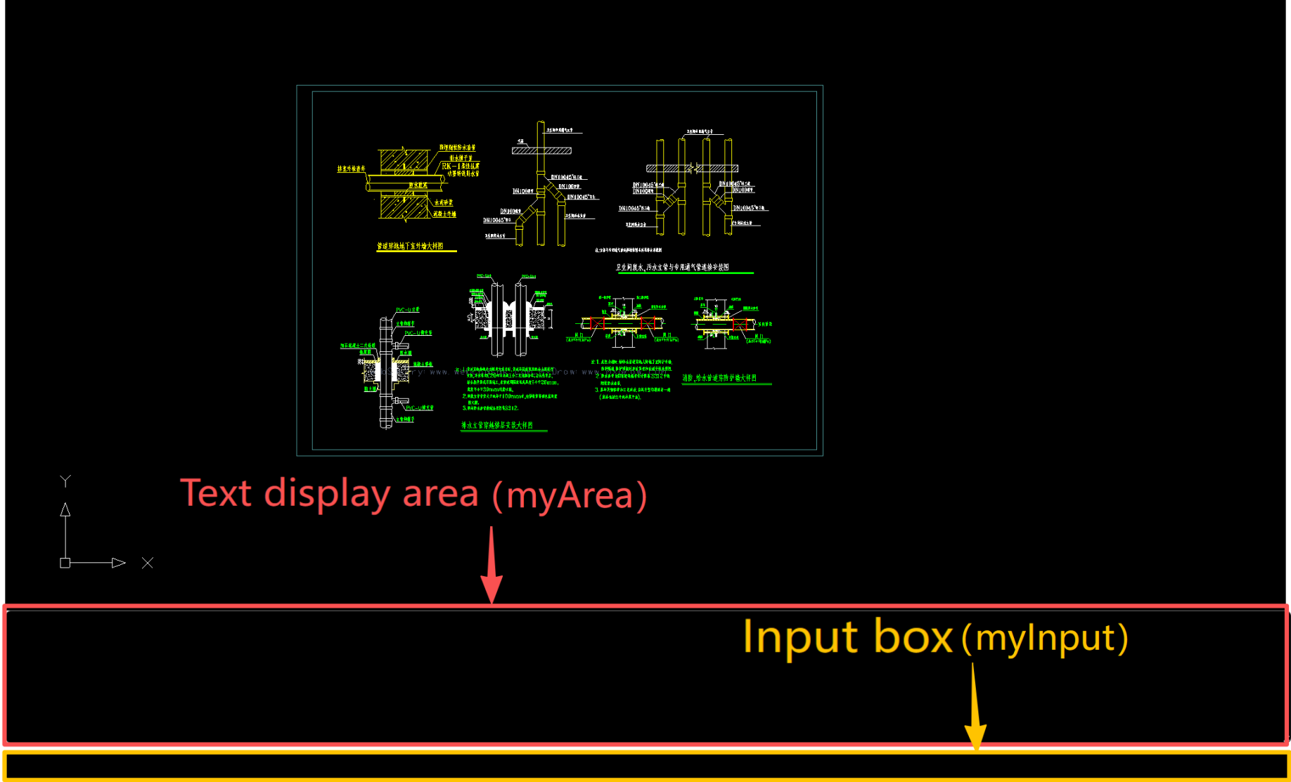
2.2 Step 2: Monitor Commands (Connect Input and Output)
With the interface, we need to make the program "understand" what the user typed in the input box and display the program's feedback in the message area.
According to the code logic in Figure 1, we need to do two things:
- Monitor User Input: When the user presses a key in the input box, tell the MxCAD kernel through
MxFun.setCommandLineInputData(). - Monitor Message Changes: When the MxCAD kernel has prompts (such as "Please click the starting point"), display these words in our message area through
MxFun.listenForCommandLineInput().
import { MxFun } from "mxdraw"

// 1. Get DOM elements: Get the input box and message display area defined in HTML
const inputBox = document.getElementById("myInput")
const cmdWindow = document.getElementById("myArea")

// 2. Monitor user input: Prepare a variable to store the current input content
let inputText = ""
inputBox.oninput = () => {
  inputText = inputBox.value
}

// 3. Monitor keyboard events: When the user presses a key (Enter or ordinary key)
inputBox.onkeydown = (e) => {
  // Pass the user's input content and key code to the MxCAD kernel for processing
  MxFun.setCommandLineInputData(inputText, e.keyCode)

  // If the Enter key is pressed (keyCode 13), it means the command is sent
  if (e.keyCode === 13) {
    // Clear the input box to prepare for the next input
    inputText = inputBox.value = ""
  }
}

// 4. Monitor kernel messages: Monitor message changes returned by the MxCAD kernel
MxFun.listenForCommandLineInput(({
  msCmdTip,      // Prompt information (e.g.: Specify next point)
  msCmdDisplay,  // Historical message display (all previous conversations)
  msCmdText      // Current command text
}) => {
  // Splice the messages returned by the kernel and display them in our HTML element
  cmdWindow.value = msCmdDisplay + "\n" + msCmdTip
  // Automatically scroll to the bottom to ensure the user sees the latest message
  cmdWindow.scrollTop = cmdWindow.scrollHeight
})
2.3 Step 3: Register Commands (Install the Engine)
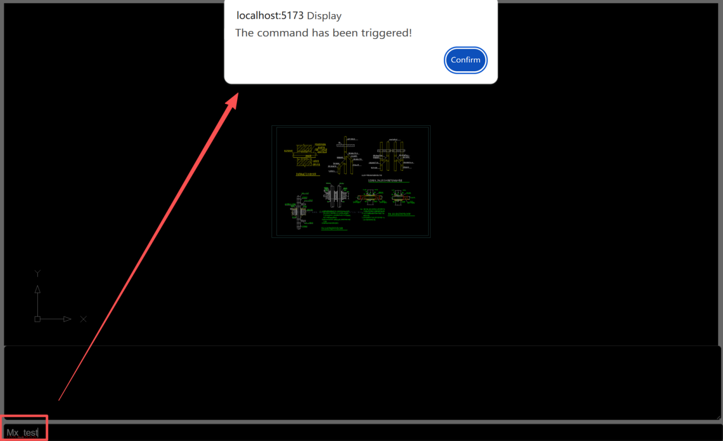
With the monitoring in place, we now need to tell MxCAD: "If the user enters a specific word (such as Mx_test), which piece of code should you execute". This is command registration.
We need to use the MxFun.addCommand() method. It's like registering a service at the front desk, telling the system: "When you hear the 'draw line' instruction, please call the 'draw line function'".
import { MxFun } from "mxdraw"

// Register command: The name is "Mx_test"
// In the future, when the user enters Mx_test in the bottom input box, the arrow function below will be executed
MxFun.addCommand("Mx_test", async () => {
  // Leave blank for now, the specific drawing logic will be written in the next section
  alert("Command triggered!");
});
2.4 Step 4: Execute Commands (Ignite and Start)
After completing the previous step, the CAD command Mx_test has been written into the mxcad object. Next, users only need to call the MxFun.sendStringToExecute() function to execute the drawing method at any time or position in the CAD project.
import { MxFun } from "mxdraw"

// Simulate user input execution: This line of code will trigger the command registered above
// Equivalent to the user entering "Mx_test" in the command line and pressing Enter
MxFun.sendStringToExecute("Mx_test");
Through the above four steps, we have successfully opened up the complete link from "user input instruction" to "program response drawing".
III. Introduction to Parametric Drawing Functions
Through the operation steps above, we have learned how to "converse" with users through the command line. But the current program still has a problem: although it understands the instructions, it is still too "rigid" when drawing.
The so-called parametric drawing is simply to make the drawing process "controllable" and "precise". We will explain this part in two stages:
- Static Parametric Drawing: Write parameters directly in the code (suitable for simple scenarios, but not flexible enough).
- Dynamic UI Interactive Drawing: When the user drags the mouse, the graphics change in real time, and specific values can be input (the standard of professional CAD).
3.1 Static Parametric Drawing: Limitations of Hard-Coded Code
The so-called "static" means that we directly specify all attributes of the graphics in the code.
Scenario Simulation: We want to draw a line. Write directly in the code:
import { MxCpp } from "mxcad";

const mxcad = MxCpp.getCurrentMxCAD(); // Get the current CAD editor instance
mxcad.newFile(); // Create a new canvas

// Draw a straight line: Coordinates and length are completely hard-coded
// This line will always be drawn from (1000, 800) to (-1000, -800)
mxcad.drawLine(1000, 800, -1000, -800)Disadvantages:
- Fixed Position: The line coordinates are fixed and cannot change according to the position clicked by the user's mouse.
- Fixed Length: The line length is fixed, and users cannot modify it by themselves according to needs.
- Poor Experience: It's like giving the user a printed drawing instead of a drawing tool.
To solve this problem, we need to introduce dynamic UI interactive drawing.
3.2 Dynamic UI Interactive Drawing: Make Graphics "Alive"
In CAD, when you click the "draw circle" command and move the mouse, the size of the circle will change in real time with the mouse until you click to confirm. This "what you see is what you get" process is dynamic interaction.
To achieve this process, we need to use the core weapon provided by MxCAD —— UI interaction API.
3.3 Introduction to Core UI Interaction APIs
In MxCAD, all interactions (drawing lines, drawing circles, selecting points) rely on MxCADUiPrBase and its subclasses (such as MxCADUiPrPoint, MxCADUiPrDist).
Core Workflow:
- Instantiation: Create an interaction object (such as a "get point" object).
- Set Prompt: Tell the user what to do (e.g., "Please specify the center of the circle").
- Execute (go): Start the interaction, the program pauses and waits for user operations.
- Get Result: After the user completes the operation, get the coordinates or numerical values.
Common API Overview:
| Class Name | Description | Use Case |
|---|---|---|
| MxCADUiPrPoint | Point input. Requests the user to click a point on the screen or enter coordinates. | Determine the starting point of a line, the position of a circle center, and the text insertion point. |
| MxCADUiPrDist | Distance input. Requests the user to enter a numerical distance, usually in conjunction with two-point measurement or direct keyboard input. | Set the radius of a circle, the width of a rectangle, and the spacing of an array. |
| MxCADUiPrAngl | Angle input. Requests the user to enter an angle value or determine the angle through two points. | Draw oblique lines, rotate objects, and set the starting angle of sectors. |
| MxCADUiPrInt | Integer input. Only accepts integer input. | Set the number of rows/columns of an array, the number of lines, and the number of sides of a polygon. |
| MxCADUiPrKeyWord | Keyword input. Provides a set of predefined options for the user to choose (such as "Yes/No", "Circle/Arc"). | Sub-option switching in commands (e.g., "3-Point(3P)/2-Point(2P)/Tangent(T)" when drawing a circle). |
| MxCADUiPrString | String input. Requests the user to enter a text string. | Enter text content, block names, layer names, and file names. |
| MxCADUiPrEntity | Entity selection. Requests the user to select an existing graphic object in the drawing. | Modify object properties, target selection for extend/trim commands, and source object for copy/move commands. |
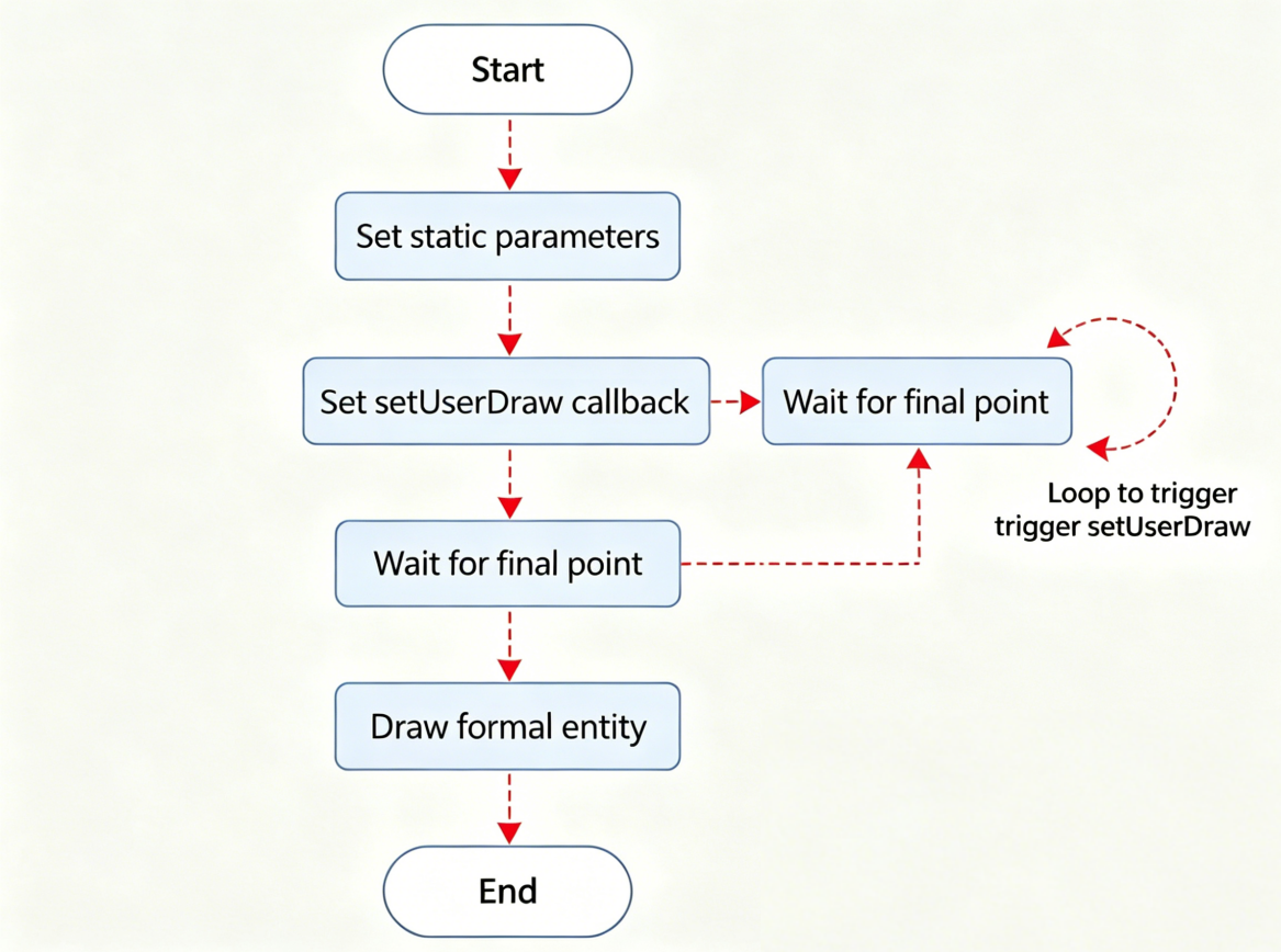
3.4 Core of Dynamic Drawing: Detailed Explanation of setUserDraw Function
Dynamic drawing is the top priority for realizing user-interactive drawing.
Many beginners will ask: "How can I display the real-time state of the current graphic on the canvas when the user moves the mouse?"
The answer is the setUserDraw function.
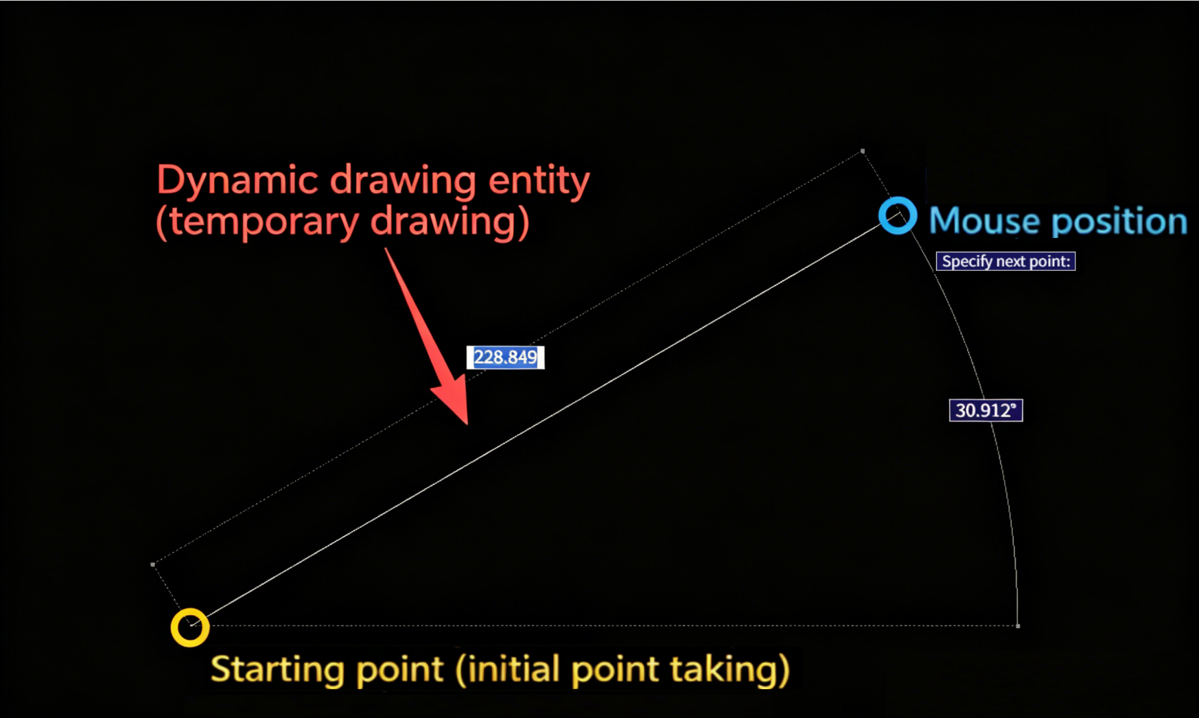
- Principle: Before the user determines the final point (such as during mouse movement), MxCAD will call this function continuously.
- Function: We write the logic of "temporary drawing" in this function. Because these graphics are drawn during the interaction process, they are usually called "rubber band graphics" or "preview graphics".
- Parameter Parsing:
currentPoint: The coordinate point where the current mouse cursor is located.pWorldDraw: Drawing context object. We need to call itsdrawMcDbEntitymethod to draw the graphics.
Note: The graphics drawn in
setUserDraware temporary. Once the interaction ends (the user clicks to confirm or cancel), these temporary graphics will be automatically cleared and will not pollute the database.
import { MxCADUiPrPoint, McDbLine } from "mxcad"
const getPoint = new MxCADUiPrPoint() // Create a get point object
getPoint.go().then((point)=> { // Get the point for the first time (starting point)
// Set dynamic drawing callback function
getPoint.setUserDraw((currentPoint, pWorldDraw)=> {
// currentPoint: Real-time changing mouse coordinates
// pWorldDraw: Drawing tool
if(!point) return // Prevent empty starting point
// 1. Create graphics: Create a line from the starting point to the current mouse point
const line = new McDbLine(point, currentPoint)
// 2. Draw graphics: Draw this line on the screen (temporarily)
pWorldDraw.drawMcDbEntity(line)
})
// Wait for the second click (end point)
// During the waiting period, the above setUserDraw will be triggered frequently to achieve the "drag preview" effect
getPoint.go()
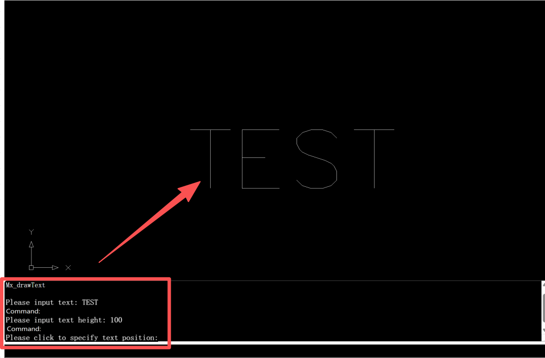
})3.5 Detailed Explanation of a Complete Dynamic Drawing Example: Drawing Interactive Text
In the previous introduction, we understood the principle of dynamic drawing. Now, let's connect all the knowledge points through a specific example —— "drawing text".
In this case, we will implement a complete interaction process:
- Input Content: Users enter text content through the keyboard.
- Input Height: Users determine the text height by mouse dragging or keyboard input.
- Dynamic Preview: When the user moves the mouse, the text follows the cursor for real-time preview.
- Fixed-Point Generation: The user clicks the mouse to permanently draw the text on the drawing.
Code Implementation
import { McDbText, MxCADUiPrDist, MxCADUiPrPoint, MxCADUiPrString, MxCADUiPrBase, MxCpp } from "mxcad";

async function Mx_drawText() {
    // 1. Initialization: Create an empty text object, and we will fill its data later
    const text = new McDbText();

    // --- Step 1: Get text content ---
    // Create an interactive object for "getting strings"
    const getStr = new MxCADUiPrString();
    // Set command line prompt
    getStr.setMessage("Please enter text content:");
    // Wait for user input (await will pause the function until the user presses Enter or cancels)
    const str = await getStr.go();
    // If the user presses Esc to cancel, exit the function directly
    if (!str) return;
    // Assign the content entered by the user to the text object
    text.textString = str;

    // --- Step 2: Get text height ---
    // Create an interactive object for "getting distance"
    const getDist = new MxCADUiPrDist();
    getDist.setMessage("Please enter text height:");
    // Wait for the user to enter the distance (can be by mouse dragging or keyboard input of numerical values)
    const height = await getDist.go();
    if (!height) return;
    // Assign the obtained value to the text height
    text.height = getDist.value();

    // --- Step 3: Dynamic preview and fixed point ---
    // Create an interactive object for "getting point"
    const getPoint = new MxCADUiPrPoint();
    getPoint.setMessage("Please click to determine the text position:");

    // 【Core】Set dynamic drawing callback
    // This function will be called repeatedly when the user moves the mouse
    getPoint.setUserDraw((pt, pw) => {
        // 1. Update the position of the text to the current mouse coordinates (pt) in real time
        text.position = pt;
        text.alignmentPoint = pt;
        // 2. Draw this temporary text in the preview window (pw)
        // The "rubber band" effect seen by the user is generated here
        pw.drawMcDbEntity(text);
    });

    // Wait for the user to click the mouse to determine the final position
    const position = await getPoint.go();
    if (!position) return;

    // --- Step 4: Formal drawing ---
    // Get the current CAD editor instance
    const mxcad = MxCpp.getCurrentMxCAD();
    // Add the finally determined text object to the drawing database (this step is for permanent saving)
    mxcad.drawEntity(text);
}
// --- Register command ---
// Register the function written above as a command
// Users can trigger it by entering "Mx_drawText" in the command line
MxFun.addCommand("Mx_drawText", Mx_drawText);
Code Logic Analysis
This code perfectly demonstrates the "trilogy" of parametric drawing:
- Parameter Collection (Static Phase): We used
MxCADUiPrStringandMxCADUiPrDist. These two APIs are specially used to collect necessary parameters before drawing. Note thatawaitis used here, which means the program will "pause" here to wait for user input instead of running directly, which ensures the logical order of drawing. - Dynamic Preview (Interactive Phase): This is the most exciting part. In
getPoint.setUserDraw, we do not create new graphics, but constantly modify the coordinates of the sametextobject and draw it onpWorldDraw(preview layer). It's like holding a transparent film with words written on it and moving it on the screen following the mouse. - Entity Storage (Completion Phase): After
getPoint.go()returns the final coordinates, we update the position for the last time and callmxcad.drawEntity(text). This step is equivalent to really "printing" the words on the transparent film onto the drawing.
In this way, we not only realize drawing, but also endow the drawing process with strong flexibility and professionalism.
IV. Summary
Through the study of this article, we have completed the leap from "static display" to "dynamic interaction":
- Command-Line Construction: We learned how to build a standard CAD command-line input environment through HTML layout combined with JS registration.
- Static Parametric: Understood the basis of precise drawing by calculating coordinates through code.
- Dynamic UI Interaction: Mastered core APIs such as
MxCADUiPrPointandMxCADUiPrInt, and realized a complete closed loop of "program asks questions, user answers, program draws".
Now, your CAD project has a basic professional framework, and users can input instructions at the bottom like operating AutoCAD, and draw precisely by cooperating with the keyboard and mouse.